DLS systems
Structure of DLS systems
Like any spectrometer for measurement of gases absorption spectrums Diode Laser Spectrometers (DLS) consist of tunable by frequency radiation sources – diode lasers(DL) (in prism ones it attains by diffracting screen rotation, in acoustooptical spectrometers – by scanning of acoustic waves excitation frequency in crystal, in Fourier-spectrometers – by interferometer base changing), multipass optical cells with testing gas for local measurements or optical system – telescope and reflector (mirror, subdish, ground, walls, trees, and etc., as diffuse reflectors) at telemeterings and radiation photodetector. Depending on problem complexity for measurement errors compensation as a rule in DLS systems use second supporting (reference) channel inclusive reference (etalon, standard) cell with known concentration of tested gas for compensation of errors which are determined by environment temperature changing, pressure changing, and other spatio-temporal instabilities, noises of system and any other factors which may affect on measurements accuracy. Administration of Diode lasers operation modes and registration of operating and reference channels and also results processing provided by special directed computer programs.As long as spectral range of single DL tuning as a rule is not enough for simultaneous registration of several gases, we have to use several lasers with generation frequencies that correspond to their absorption lines to measure several gases absorption.
Though this disadvantage, exactly DL provide an extremely high measurement selectivity owing to ability for generation of greatly narrow spectral line about 0,001 см-1 in comparison with typical absorption line width (1-3 см-1), e.g. methane. Positions of primary absorption lines of some molecules are coincide with several DL spectral tuning areas.
For example volt-ampere characteristics of DL of different spectral ranges are not too different, principal blocks of DLS system in a practical way remain without any modifications for local and trass variants(versions). Constructional distinctions of local and trass DLS systems in the first place are in use of multipass cells or telescopes for radiation forming.
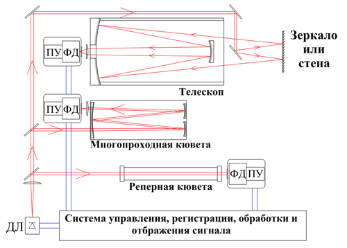
Generalized (local/trass variants)DLS spectrometer flow-chart.
Elements of DLS systems
In trass (DLST) or local (DLSL) DLS system versions with reference to the same gas are used analogous for their purpose elements and constructional distinctions appears in use of multipass cells for local measurements and telescopes for open routes(pathes) when radiation which was reflected by subdish or diffusely scattered from natural barriers (walls, trees etc.) received by the telescope. It allows to realize uniform fulfilment of DLS systems including software and electronic blocks.
Use of reference cells provides for selfcalibration (intercalibration). The ability of use fiber optics elements (radiation splitters etc.) right now allows to unify nodes of DLST and DLSL systems optical paths and also develop(build up) multifrequency DLS systems.
DLS department work is underway on application of helicopter-based(air-based) fiber optical laser spectrometers, fiber-optical amplifiers and new modifications of DL which appears on global market. Their application will allow to reach greater radiation power and as a consequence to develop aviation and satellite TDLS systems.